When procurement engineers and plant managers source a new band saw for a growing production facility, the conversation often starts with cutting capacity and ends with price. But between those two data points lies a set of calculations that determines whether the machine will integrate seamlessly into your factory floor or become a costly bottleneck: throat depth, gap height, and motor horsepower.
These three specifications govern the physical limits of what your saw can cut, the power it needs to cut it, and the floor space it demands to operate efficiently. Miscalculate any one of them, and you risk ordering a machine that cannot accommodate your largest workpieces, stalls on hard alloys, or blocks critical material-handling aisles. This sourcing blueprint provides the formulas, reference tables, and decision frameworks that B2B buyers need to perform machinery throat depth and gap height calculation with engineering precision—before the purchase order is signed.
Whether you are scaling from a single semi-automatic saw to a multi-machine cutting cell or sourcing an automatic shuttle feed bandsaw machine from a manufacturer, this guide walks through every calculation step. For a broader overview of available machine configurations, see our guide to different bandsaw machine types.
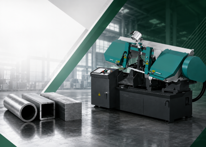
Throat depth is the horizontal distance between the saw blade and the nearest vertical obstruction on the machine frame—typically the column or the blade guard housing. On a horizontal band saw, this dimension determines the maximum width of material that can pass through the cutting zone without interference. On a vertical band saw, it defines the widest workpiece that can be maneuvered between the blade and the frame.
Throat depth is directly related to the wheel diameter of the band saw. The two wheels that drive the blade are housed within the frame, and the distance from the blade to the frame column is approximately equal to the wheel radius minus the blade guard clearance. This is why a “14-inch band saw” typically offers a throat depth of about 13.5 inches—the nominal size refers to the wheel diameter, and the usable throat is slightly less due to frame and guard geometry.
To determine the minimum throat depth your operation requires, identify the widest cross-section of material you will ever process and add a clearance margin:
Required Throat Depth = Maximum Material Width + (10% to 15% Clearance Margin)
The clearance margin accounts for blade guard protrusion, workpiece irregularities, and the need to position material without binding against the frame. For operations cutting standard round bars, the “width” is simply the bar diameter. For rectangular stock, structural shapes, or bundle cutting, use the widest dimension of the clamped bundle.
For example, if your largest workpiece is a 400 mm wide structural I-beam, the minimum throat depth should be 440–460 mm. Selecting a machine with a throat depth that barely matches your maximum material size leaves no room for error and can force operators to reposition material mid-cut, reducing throughput and increasing safety risks.
| Max Material Width | Clearance Margin (12.5%) | Minimum Required Throat Depth |
|---|---|---|
| 200 mm (7.87 in) | 25 mm | 225 mm |
| 350 mm (13.78 in) | 44 mm | 394 mm |
| 500 mm (19.69 in) | 63 mm | 563 mm |
| 700 mm (27.56 in) | 88 mm | 788 mm |
| 1,000 mm (39.37 in) | 125 mm | 1,125 mm |
For guidance on matching cutting capacity to your material profile, see our article on what industrial bandsaw size you need.
Gap height—also called resaw height or maximum cutting height—is the vertical clearance between the worktable or vice surface and the lowest point of the upper blade guide assembly. This dimension determines the maximum thickness (or height, in the case of horizontal saws) of material the machine can accommodate for a through-cut.
On a horizontal band saw, gap height translates to the maximum height of the workpiece that can be secured in the vice and cut in a single pass. On a vertical band saw, it defines how thick a board or plate can be sliced vertically. In both cases, the gap height is an adjustable dimension—the upper blade guide can be raised or lowered—but the maximum gap is fixed by the machine’s frame geometry.
The calculation for gap height follows the same principle as throat depth, but applies to the vertical dimension:
Required Gap Height = Maximum Material Height + Blade Guide Clearance (typically 25–50 mm)
The blade guide clearance ensures the upper guide assembly does not contact the workpiece during the cut. For horizontal saws processing round bars, the “height” is the bar diameter. For rectangular stock or bundles, use the tallest dimension of the clamped material. When planning for bundle cutting, calculate the total bundle height including the spacing between bars.
Critical consideration: gap height and throat depth are interdependent. A machine with a 500 mm throat depth but only 300 mm gap height cannot cut a 500 mm square billet—it can accommodate the width but not the height. Always verify that both dimensions exceed your largest workpiece profile. For a structured approach to evaluating these specifications, review our Industrial Bandsaw Machine Selection Guide.
Motor horsepower (or kilowatt rating) determines whether your band saw can maintain consistent blade speed under load. Insufficient power causes the blade to slow down when cutting dense or thick materials, generating excess friction, thermally binding the blade, and producing poor cut quality. In high-volume operations, underpowered saws also suffer from accelerated gearbox wear and frequent blade breakage.
The band saw motor power specification you need depends on three variables: the material’s specific cutting force (a measure of how much energy is required to remove a unit volume of material), the cross-sectional area being cut, and the desired penetration rate. Harder alloys require significantly more power per unit of material removed.
Industrial engineers use the material removal rate (MRR) method to estimate required cutting power. The formula is:
Required Power (kW) = (MRR × Specific Cutting Force) / 60,000
Where MRR is measured in cubic centimeters per minute (cm³/min) and specific cutting force (KC) is measured in N/mm². The specific cutting force varies dramatically by material:
| Material Group | Specific Cutting Force (N/mm²) | Relative Power vs. Aluminum |
|---|---|---|
| Aluminum | 750 | 1.0x (baseline) |
| Cast Iron | 1,285 | 1.7x |
| Low-Carbon Steel | 1,350 | 1.8x |
| Alloy Steel | 1,750 | 2.3x |
| Stainless Steel (Austenitic) | 2,150 | 2.9x |
| Tool Steel | 2,475 | 3.3x |
| Titanium Alloys | 3,000–3,300 | 4.0–4.4x |
| Nickel-Based Superalloys | 3,300+ | 4.4x+ |
This table reveals why a saw that cuts aluminum effortlessly may stall on titanium. Cutting titanium bars requires approximately four times the motor power of cutting aluminum at the same penetration rate. For operations processing hard alloys, a 20% torque safety margin above the calculated requirement is recommended to protect gearbox life and accommodate blade wear, which can increase cutting force by up to 50% as teeth dull.
Based on these specific cutting force values, the following motor power ranges are recommended for industrial horizontal band saws:
| Material Profile | Recommended Motor Power | Representative KEENSAW Model |
|---|---|---|
| Structural shapes, mild steel tubes, aluminum | 3.0–5.5 kW (4–7.5 HP) | GZ4028 / GZ4252 |
| Solid round bars, stainless steel, medium alloys | 5.5–7.5 kW (7.5–10 HP) | 530BCNC CNC |
| Tool steel, large billets, titanium, superalloys | 11 kW+ (15 HP+) | BSV7050CNC |
KEENSAW, as a cnc automatic metal cutting bandsaw manufacturer, designs each machine with motor power matched to its intended cutting capacity range. The BSV7050CNC, for example, pairs an 11 kW motor with a heavy-duty frame to deliver the sustained torque needed for high-volume processing of solid tool steel and large-diameter alloy billets.
Motor horsepower is only half the power equation. The high torque reduction gearbox sitting between the motor and the blade wheels is what converts high-speed, relatively low-torque motor output into the low-speed, high-torque rotational force that drives the blade through dense metal. Without an adequately rated gearbox, even a powerful motor cannot deliver the cutting force needed for hard alloys.
A reduction gearbox uses a series of gears to reduce the output speed of the motor while proportionally increasing torque. In a typical industrial band saw, the motor runs at 1,450 or 2,900 RPM, but the blade wheels need to turn at a much lower speed—often 50 to 200 RPM depending on the desired blade speed (measured in meters per minute). The gearbox achieves this reduction through helical gears, worm gears, or planetary gear sets, each offering different trade-offs in efficiency, torque capacity, and maintenance requirements.
Gearbox efficiency matters because power is lost in the transmission process. A typical gear-driven band saw operates at 70–80% mechanical efficiency, meaning a 7.5 kW motor delivers approximately 5.3–6.0 kW of effective cutting power at the blade. This efficiency loss must be factored into the motor sizing calculation—a machine that needs 6 kW at the blade requires at least a 7.5–8.6 kW motor when using a gear-driven transmission.
Modern industrial band saws pair the reduction gearbox with a Variable Frequency Drive (VFD) to achieve precise blade speed control. The gearbox provides the base reduction ratio, while the VFD allows operators to fine-tune the motor speed to match the material being cut. This combination delivers three benefits:
When evaluating a large capacity heavy duty horizontal bandsaw from a manufacturer, verify that the gearbox torque rating exceeds your calculated cutting torque by at least 20%. This margin protects the gears during blade binding events and accommodates the increased cutting force that occurs as the blade dulls between changes. For operations cutting titanium or superalloys, a planetary gearbox with a minimum service factor of 1.5 is recommended.
The static machine dimensions on a data sheet represent only 40–60% of the total floor space a band saw actually requires. A thorough bandsaw workshop footprint planning assessment must account for the dynamic operational envelope: the material feeding shuttle stroke, electrical cabinet door clearance, chip conveyor extension, coolant tank access, and the safety perimeter needed for overhead crane or forklift access.
Industrial engineering practice uses a multiplier formula to estimate total required floor area:
Total Floor Area = Machine Length × Machine Width × Multiplier Factor (K)
The multiplier factor (K) ranges from 1.6 to 2.5 depending on the level of automation and material handling complexity:
| Automation Level | Multiplier (K) | Additional Space Drivers |
|---|---|---|
| Manual / Semi-automatic saw | 1.6–1.8 | Operator zone, manual material staging, basic chip bin |
| Automatic saw with shuttle feed | 1.9–2.2 | Shuttle stroke length, roller conveyor, hydraulic power unit |
| Fully automated cutting cell | 2.2–2.5 | Loading racks (6m+), outfeed sorting, bundle clamping, safety fencing |
Consider a factory installing a KEENSAW 530BCNC automatic band saw (machine dimensions: 3,100 × 2,300 mm) with hydraulic shuttle feed and a 6-meter bar loading rack. The calculation proceeds as follows:
Step 1: Machine base footprint = 3.1 m × 2.3 m = 7.13 m²
Step 2: Apply multiplier for automatic saw with shuttle feed (K = 2.1) = 7.13 × 2.1 = 14.97 m²
Step 3: Add loading rack length (6 m × 1.5 m width) = 9.0 m²
Step 4: Add operator aisle (1,200 mm pedestrian + 1,500 mm forklift access along one side) = 3.1 m × 2.7 m = 8.37 m²
Step 5: Total estimated floor area = 14.97 + 9.0 + 8.37 = 32.34 m²
This total—roughly 4.5 times the machine’s base footprint—reflects the real-world space demand of an automatic sawing cell. Failing to allocate this space before installation leads to blocked aisles, unsafe material handling, and lost productivity. For a detailed walkthrough of footprint, motor, and material handling considerations, see our industrial horizontal band saw sourcing guide.
Beyond the total floor area, specific clearance dimensions must be maintained around the machine:
As an experienced automatic shuttle feed bandsaw machine manufacturer, KEENSAW provides custom floor layout configurations and technical consultation to help buyers plan their factory floor space before installation.
Throat depth, gap height, motor power, gearbox torque, and floor space are not independent variables—they form an integrated specification framework. The following checklist synthesizes all calculations into a single sourcing decision tool:
| # | Sourcing Checkpoint | Calculation or Benchmark | Action If Requirement Not Met |
|---|---|---|---|
| 1 | Throat depth exceeds max material width? | Max width × 1.125 | Select larger model or limit material range |
| 2 | Gap height exceeds max material height? | Max height + 25–50 mm guide clearance | Select larger model or add riser block |
| 3 | Motor power sufficient for hardest material? | MRR × KC / 60,000 + 20% safety margin | Upgrade motor or reduce feed rate |
| 4 | Gearbox torque rating adequate? | Service factor ≥ 1.5 for hard alloys | Select model with heavier gearbox |
| 5 | VFD included for variable blade speed? | Required if cutting multiple material types | Add VFD as option or choose CNC model |
| 6 | Floor area allocated ≥ machine footprint × K? | K = 1.6–2.5 by automation level | Re-layout floor or select compact model |
| 7 | Loading rack length ≥ longest bar stock? | Bar length + 500 mm buffer | Extend rack or pre-cut stock to length |
| 8 | Aisle width meets forklift turning radius? | 1,500–2,000 mm minimum | Relocate machine or use alternative handling |
If any checkpoint reveals a shortfall, the cost of addressing it before purchase is a fraction of the cost of retrofitting after installation. KEENSAW’s engineering team provides personalized consultation to validate these calculations against your specific material profile and facility constraints. For operations scaling to high-volume production, also review our analysis of heavy-duty dual-column band saws for large billets and our guide on why you need a bandsaw machine.
The ideal motor horsepower for cutting titanium bars depends on the bar diameter and desired cutting speed, but as a baseline, a minimum of 7.5 kW (10 HP) is recommended for titanium rounds up to 200 mm, and 11 kW (15 HP) or more for diameters above 300 mm. Titanium alloys have a specific cutting force of approximately 3,000–3,300 N/mm²—roughly four times that of aluminum—meaning the saw must deliver sustained high torque at low blade speeds (15–25 m/min). A machine like the KEENSAW BSV7050CNC with its 11 kW motor and VFD speed control is engineered for this application. Always apply a 20% torque safety margin above the calculated requirement to accommodate blade wear.
To calculate factory floor space for automatic sawing equipment, use the formula: Total Floor Area = Machine Length × Machine Width × Multiplier Factor (K), where K ranges from 1.9 to 2.5 for automatic saws depending on automation complexity. Add the loading rack area (bar length × rack width), operator and forklift aisle space (minimum 1,200–1,500 mm wide), and safety perimeter clearance. For example, a machine with a 3,100 × 2,300 mm footprint, a 6-meter loading rack, and standard aisles typically requires 30–35 m² of total floor space—roughly 4.5 times the machine’s base footprint. Always validate the calculation against your facility’s structural columns, utility routing, and ceiling height before installation.
Throat depth is the horizontal distance between the saw blade and the nearest vertical frame obstruction, determining the maximum material width that can pass through the cutting zone. Gap height (also called resaw height or maximum cutting height) is the vertical clearance between the worktable or vice surface and the upper blade guide, determining the maximum material thickness or height. Both dimensions must independently exceed your largest workpiece profile—a machine with adequate throat depth but insufficient gap height cannot cut a large square billet, regardless of its width capacity.
Calculate required throat depth using the formula: Required Throat Depth = Maximum Material Width × 1.10 to 1.15 (10–15% clearance margin). The clearance margin accounts for blade guard protrusion, workpiece irregularities, and positioning tolerance. For round bars, use the diameter as the “width.” For rectangular stock, structural shapes, or bundle cutting, use the widest dimension of the clamped bundle. For example, a 400 mm wide I-beam requires a minimum throat depth of 440–460 mm. Always verify that the machine’s specified throat depth exceeds this calculated value before purchase.
Stainless steel (austenitic grades) has a specific cutting force of approximately 2,150 N/mm²—roughly 2.9 times that of aluminum. For cutting stainless steel rounds up to 300 mm, a minimum motor power of 5.5–7.5 kW (7.5–10 HP) is recommended. For larger diameters or high-volume production, 7.5–11 kW is preferred. The motor must be paired with a reduction gearbox that maintains adequate torque at the low blade speeds (25–40 m/min) required for stainless steel. KEENSAW’s 530BCNC with its 7.5 kW motor and VFD-controlled blade speed is well suited for stainless steel cutting applications.
A high torque reduction gearbox converts the motor’s high-speed, low-torque output into the low-speed, high-torque rotational force needed to drive the blade through dense metal. Without an adequately rated gearbox, even a powerful motor cannot deliver sufficient cutting force at the low blade speeds required for hard materials. The gearbox also determines the machine’s mechanical efficiency (typically 70–80% for gear-driven systems), which must be factored into motor sizing. For operations cutting titanium, tool steel, or superalloys, the gearbox should have a minimum service factor of 1.5 to handle the increased cutting forces and accommodate blade binding events without gear damage.
A VFD improves band saw performance by allowing operators to continuously adjust blade speed to match the material being cut, without requiring belt changes. It provides three key benefits: optimized cutting speed for each alloy (e.g., 70+ m/min for aluminum versus 15–25 m/min for titanium), soft-start protection that eliminates mechanical shock to the gearbox during motor startup, and maintained torque output at reduced speeds for cutting hard materials. When paired with a high torque reduction gearbox, a VFD-controlled motor delivers both the speed flexibility and the sustained cutting force needed for mixed-material production environments.
For an automatic band saw with hydraulic shuttle feed, use a multiplier factor (K) of 1.9–2.2 applied to the machine’s base footprint (Length × Width). For fully automated cutting cells with loading racks, outfeed sorting, and safety fencing, use K = 2.2–2.5. The multiplier accounts for the shuttle feed stroke, electrical cabinet clearance, chip conveyor extension, operator aisles, and material staging areas. For example, a machine with a 7.13 m² base footprint and K = 2.1 requires approximately 15 m² of operational floor space—before adding loading rack and aisle areas. Always validate the total against your facility layout before purchase.
Yes, but only if the machine is equipped with a VFD (Variable Frequency Drive) and a sufficiently powerful motor. Aluminum requires high blade speeds (60–90 m/min) and relatively low torque, while titanium requires low blade speeds (15–25 m/min) and high torque—approximately four times the cutting force per unit volume. A machine with a 7.5 kW or larger motor, VFD speed control, and a high torque reduction gearbox can handle both materials by adjusting blade speed and feed rate. Without a VFD, the speed range may be too narrow to optimize cutting for both alloys, leading to poor blade life on one or both materials. KEENSAW’s CNC automatic band saws are designed for this type of mixed-material flexibility.
Verify manufacturer specifications by cross-checking four data points against your calculated requirements: (1) throat depth must exceed your maximum material width plus 10–15% clearance, (2) gap height must exceed your maximum material height plus 25–50 mm blade guide clearance, (3) motor power must exceed the MRR × KC calculation plus a 20% safety margin for your hardest material, and (4) the gearbox service factor must be ≥ 1.5 for hard alloy cutting. Request the manufacturer’s detailed specification sheet and ask for a custom floor layout drawing showing the total operational envelope including loading rack, aisles, and maintenance access. As an experienced large capacity heavy duty horizontal bandsaw manufacturer, KEENSAW provides these engineering documents as part of the sourcing consultation process.
Existing guides on KEENSAW:
Recommended future articles:
Need help calculating the right throat depth, gap height, and motor power for your production facility? Contact KEENSAW today for a personalized sourcing consultation with our engineering team.
Contact us if you have any questions we will reply as soon aspossible